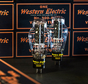
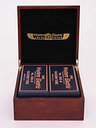
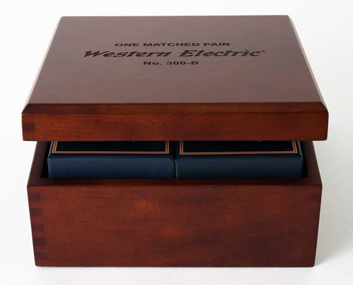
Western Electric 300B Vacuum Valve Hand Selected Quad Set (4 pcs.)


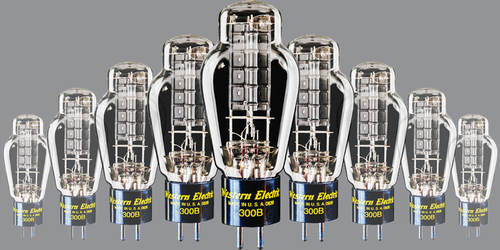


Легендарный прямонакальный вакуумный триод, одна из лучших ламп для применения в усилителях звуковой частоты. Обладает исключительной линейностью характеристики при относительно умеренных анодном напряжении (200-450 В) и потреблении накалом (5 В, 1,2 А) по сравнению с другими прямонакальными триодами типа 211 или 845, требующих анодного напряжения свыше киловольта. С одной лампы в однотактной схеме усилителя класса А1 можно получить до 9 Вт, в классе А2 (с заходом в область сеточных токов) – до 20 Вт. Эти лампы имеют особый звуковой почерк с характерной для них прозрачностью, четкостью артикуляцией и локализацией в пространстве и сбалансированным тональным балансом.
С помощью современных технологий уникальное качество 300B выпуска 1938-1986 годов удалось вывести на еще более высокий уровень в современном производстве. Так, сборка производится в стерильном корпусе с мощными фильтрующими воздух установками Hepa, сварка электродов осуществляется в атмосфере чистого азота. Сверхмощные насосы обеспечивают предельно достижимую степень вакуума в баллонах ламп. Катод / накал изготовляется из специального сплава, разработанного на заводе в Чикаго в 1963 году. Эмиссионный слой оксида наносится на катод по специальной технологии, изначально разработанной для производства кабелей связи, которые прокладывали по дну океана, что гарантирует механическую прочность и долговечность наряду с высокой эмиссионной способностью при умеренных температурах нагрева. Катод покрывается слоем патентованного состава. Готовые лампы проходят необходимую тренировку и строгий отбор по параметрам.
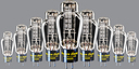
Оригинальные 300B производства Western Electric намного превосходят любые другие аналоги данной лампы. Предлагаются как в единичных экземплярах, так и в строго подобранных парах и квартетах.
Основные особенности модели Western Electric 300B Vacuum Valve:
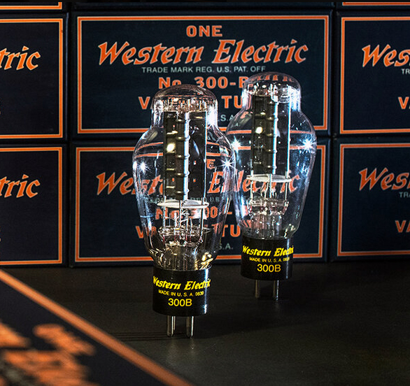
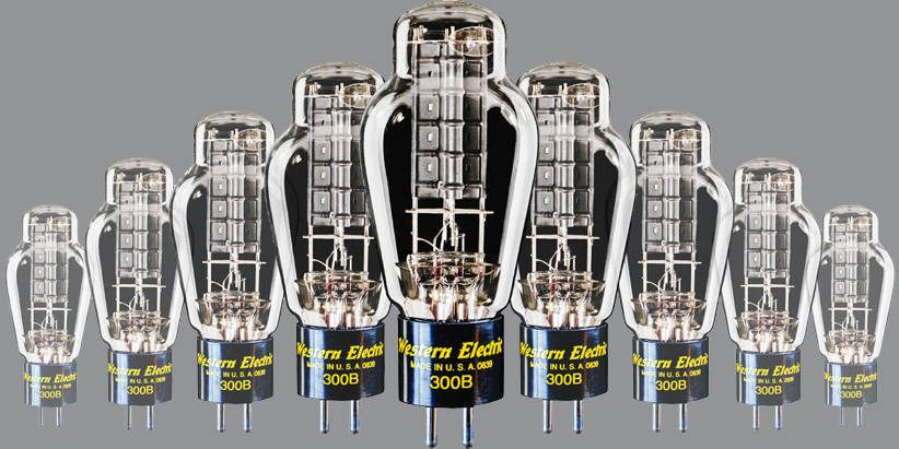
- Прямонакальные вакуумные триоды 300B
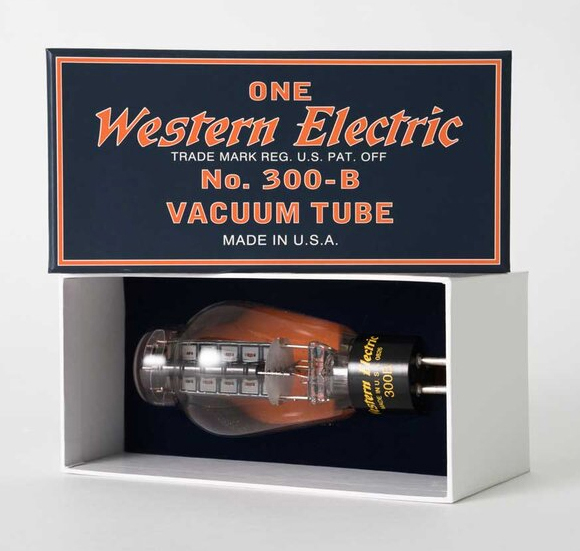
- Оригинальное производство Western Electric
- Улучшенные параметры ламп при сохраненной классической конструкции
- Патентованный материал катода / накала
- Высокоэффективный и долговечный эмиссионный покров катода
- Тренировка, тщательный выходной контроль
- Точная подборка по параметрам в пары и квартеты
Classification
Moderate power, filamentary triodes for Class-A service.
Application
Audio-frequency amplifier in positions where power outputs of approximately ten watts or less are required at relatively low plate voltages.
Dimensions
Dimensions, outline diagrams of the tubes and bases, and the arrangement of electrode connections to the base terminals are shown in Figures 1 and 2.
Base and Mounting
These vacuum tubes employ medium, four-pin thrust type bases suitable for use in Western Electric 143B or similar sockets. The 300B tube has the bayonet pin so located that it may also be mounted in a Western Electric 100M, 115B, or similar socket.
The tubes may be mounted in either a vertical or horizontal position. If mounted In a horizontal position, the plane of the filament, which is indicated In Figure 2, should be vertical.
Average Direct Interelectrode Capacitances
Grid to plate 15 µµf.
Grid to filament 9 µµf.
Plate to filament 4.3 µµf.
Filament Rating
Filament voltage 5.0 volts, a.c. or d.c.
Nominal filament current 1.2 amperes
The filaments of these tubes are designed to operate on a voltage basis and should be operated at as near the rated voltage as possible. When alternating current is used for heating the filament, the grid and plate returns should be connected to a center tap on the secondary of the filament transformer.
CHARACTERISTICS
Average Characteristics
(Ef = 5.0 volts, a.c., Eb = 300 volts and Ec = -61 volts)
Plate current 60 milliamperes
Amplification factor 3.85
Plate resistance 700 ohms
Grid to plate transconductance 5500 micromhos
Limiting Operating Conditions for Safe Operation
(Not simultaneous ratings)
Maximum plate voltage: 450 volts
Maximum plate dissipation: 40 watts
Maximum plate current of an average tube for fixed grid bias: 70 milliamperes
Maximum plate current for manually adjusted grid bias or self-biasing circuit: 100 milliamperes
Recommended Operating Conditions
Recommended and maximum conditions for alternating-current filament supply are given in the table. Recommended conditions or others of no greater severity should be selected in preference to maximum conditions wherever possible. The life of the tube at maximum operating conditions will be shorter than at the recommended conditions.
Where it is necessary to operate the tube at or near the maximum plate current of 100 milliamperes, provision should be made for adjusting the grid bias of each tube independently, so that the maximum safe plate current will not be exceeded in any tube. Alternatively, a self-biasing circuit may be used, in which the grid bias for the tube is obtained from the voltage drop produced by the plate current of that tube flowing through a resistance.
Where it is necessary to use a fixed grid bias, the plate current of the average tube should be limited to a maximum value of 70 milliamperes, so that tubes having plate currents higher than the average will not exceed the maximum safe plate current.
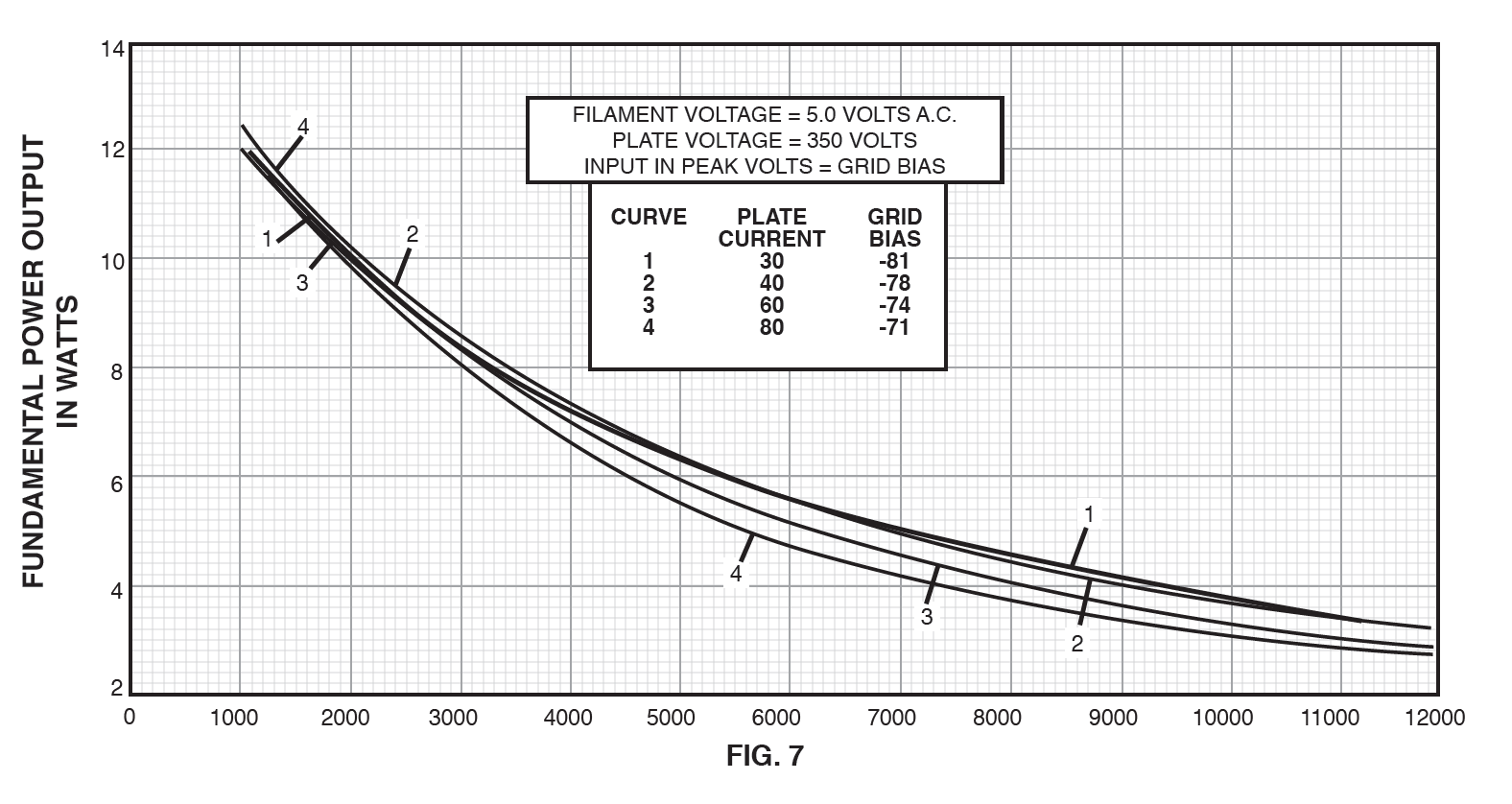
Power Output and Distortion
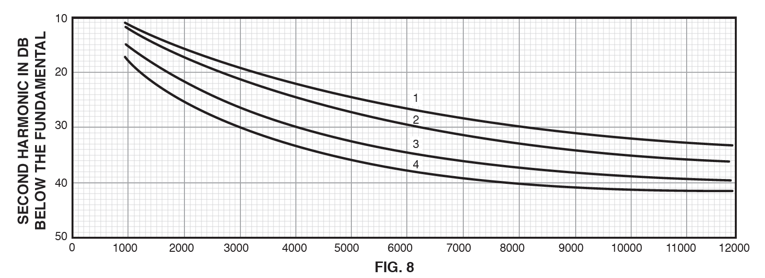
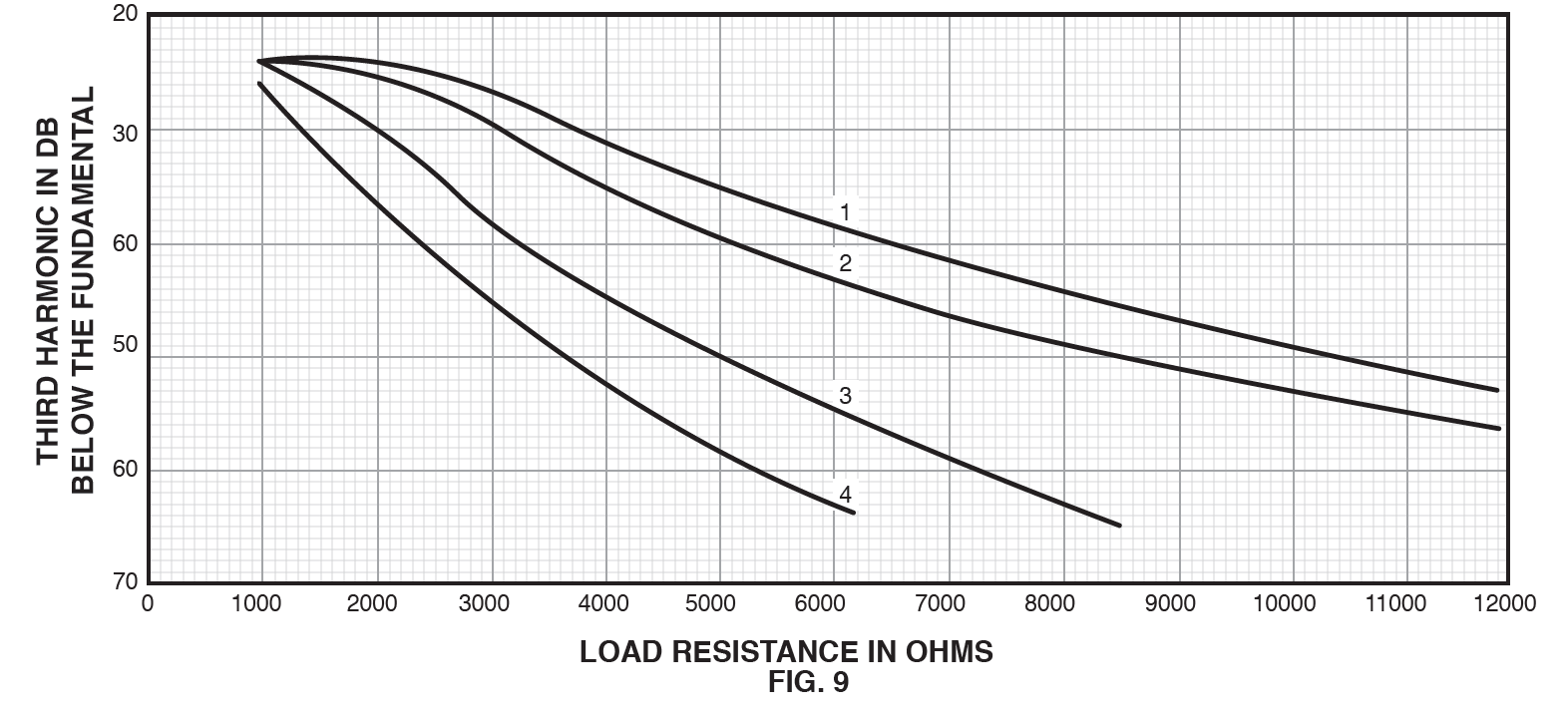
Performance data including power output, second and third harmonic levels for a number of operating conditions are given in the table.
The variation of power output and harmonic levels with load resistance for several values of operating plate current is shown in Figures 7, 8 and 9, for a plate voltage of 350 volts.
The peak value of the sinusoidal input voltage, Egm, which gives the indicated power output, Pm and harmonic levels, F2m and F3m for each point in both the curves and the table, is numerically equal to the grid biasing voltage at that point. For a smaller input voltage Eg, the approximate levels may be computed from the following relations.
P=Pm(Eg/Egm)^2
F2=F2m+20 log10(Eg/Egm)
F3=F3m+40 log10(Eg/Egm)
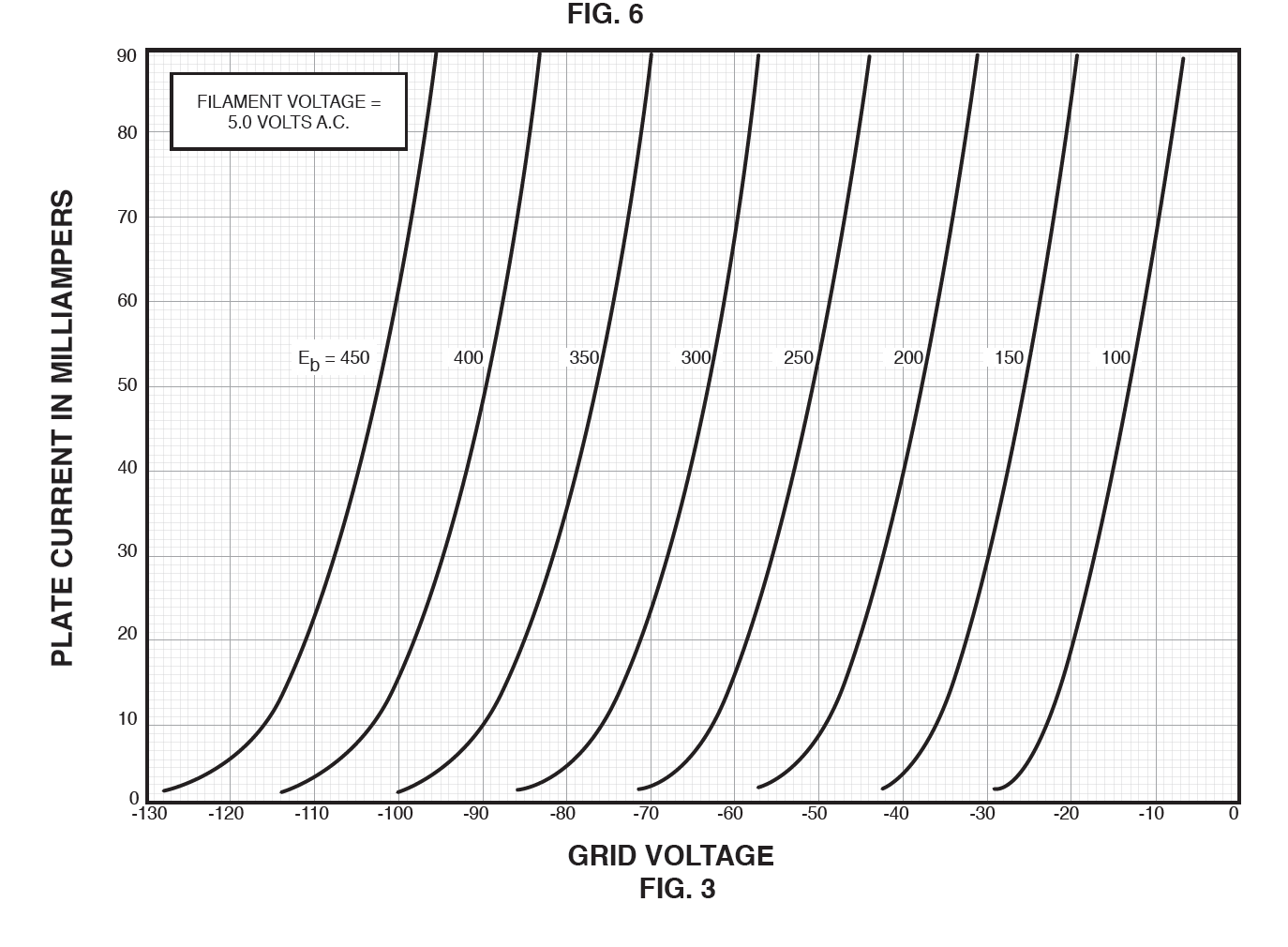
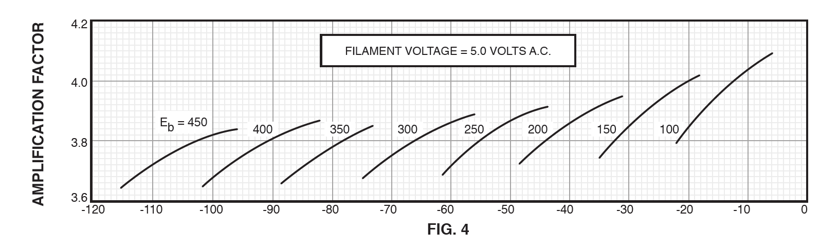
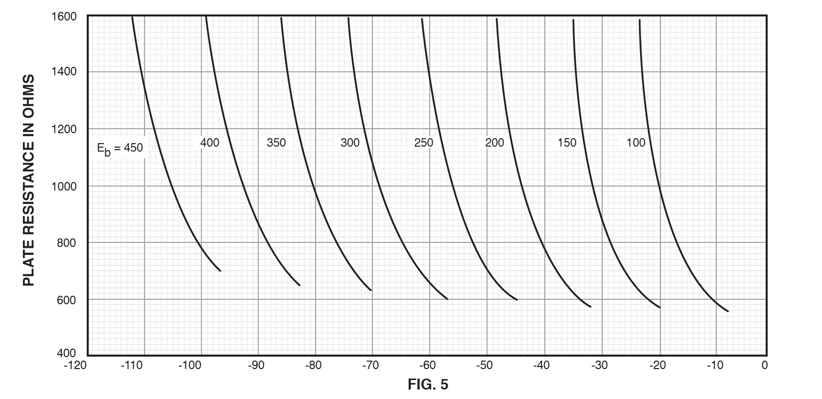
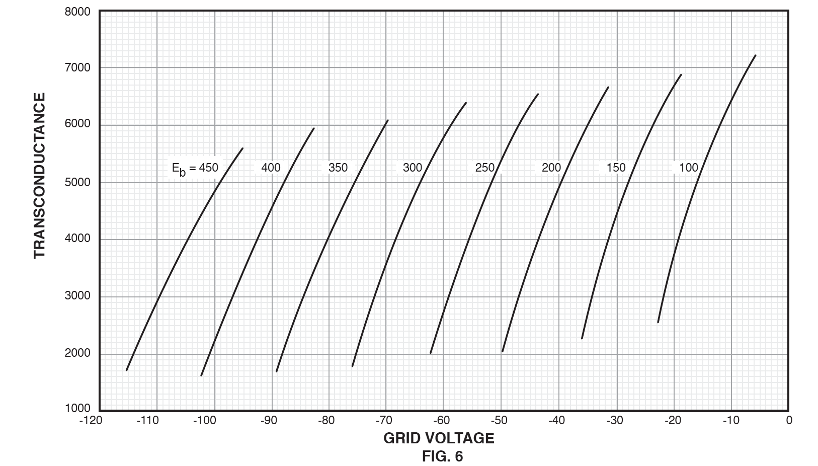
CHARACTERISTIC CURVES
Plate-current characteristics for a typical tube are shown in Figure 3 as functions of grid bias, for alternating-current filament supply. The corresponding amplification-factor, plate-resistance, and transconductance characteristics are given in Figures 4, 5 and 6, respectively. When direct-current filament supply is used, and the grid and plate returns are connected to the negative end of the filament, the same characteristics are applicable if 3.5 is subtracted from the numerical value of each grid bias.